PICTURES OF DIGITAL CONTROL DEVICES
Click on any small picture to expand it. Click on any large picture to return to this screen.
S
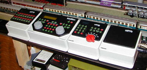
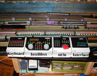
everal pictures of the Uhlenbrock/Modeltreno Intellibox (650) with a Märklin Keyboard, a Märklin Control 80f and a Märklin Interface all connected. The Märklin Interface has an Modellbahn Ott Infra-red Receiver and Controller connected to it. The Intellibox is connected to a computer and TPL is used to control trains from this program. Using the Intellibox with a Märklin (6036) Contol 80f allows you to control three engines at the same time. Setting the Marklin Keyboard allows me to set the Keyboard to a frequently set group of switches for fast setting. The Intellibox allows me to control all of my switches by setting groups of 8 switches at a time.I added the Intellibox Controller/Remote Control unit (654) which connects to the main IB through the one of the loconet ports allowing control of an additional two more loks from almost any point on the layout. This is a great addition. It gives me control of two more engines and at a distance from the IB.
I have also added the IB Switch which serves as a keyboard that allows 40 switches or signals to be set from the keyboard. It also allows routes to be set. The keyboard can be programmed for the most frequently used switches and not in sequential order.
I have added a Loco Net bus around the layout so that I can attach the IB Control and the IB Switch in different locations. I have installed dual ports that daisy chain one to another for this purpose.
I added two FRED's to my list of control devices allowing me to control up to 4 loks with each FRED. Once programmed a FRED will allow control of the four specified loks. If you want it to control a different set of loks it must be reprogrammed for these new loks. Programming loks must be done directly with the IB and not the IB Control. I have simply added a port next to the IB for this purpose.
After purchasing the FRED's Uhlenbrock released the DAISY which allows the control of 16 loks and 260 switches or signals. You can always change the loks you have designated for control by the DAISY. This unit made the FRED obsolete. The DAISY has an LED that allows you to see the lok/turnout/signal that has been selected. The DAISY has four function keys like the FRED. It plugs into the LocoNet and is movable like the FRED. The DAISY is a really great addition to my control devices. I intend to add one or two more for mobile control of my layout.
I have added the Uhlenbrock IRIS (an infra-red unit) that allows control of four different loks. You can select the loks, they are not permanent. Functions from F1 to F12 can be controlled. You can also set any four sequential turnouts. Routes set by the IB can be run. The IR does not have a display but you can set the IB to show the lok and turnouts being controlled on the IB in the center of the display. You must have an IB with Version 1.500 firmware or higher to operate the IRIS. This is a very versatile and powerful control addition to my layout. It allows me to go to a lok that might have derailed, correct the problem, and take control of the lok at that point. Also, when working under your layout, if you want to test a turnout, the IRIS is the unit to have with you. No more crawling out from under the layout to go to the IB. Of course you can also take a Daisy under with you is the cable will reach and do the same thing.
I have added the Uhlenbrock Profi-Control unit which is a train cab controller. It simulates the control devices in the cab of a diesel or electric lok. It is actually two FRED's. With this device you feel like you are driving a train. You must use several levers and a speed control wheel to drive the train just as you would in the cab of a real lok. It is a lot of fun to use. You can preselect up to 8 loks but you can only run one at a time using the Profi-Control.
S
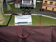
everal pictures of the Uhlenbrock S88 (63 350) for three rail AC. Since I have a large layout and I use computer control it is essential that I have a number of contact tracks to send signals back to the computer as a train occupies the track section. To interface with the computer you need Märklin S88 units which receive the signal and pass it to the computer through the IB or a Märklin control unit. The big problem with Märklin's S88's is the fact that they must be daisy-chained and the ribbon cables used to do this are short, really short. For that reason you must run long single wires from any contact track to the nearest S88.Uhlenbrock has solved that problem with its S88 unit. They plug into a LocoNet, which I have installed. All you need do is program the S88 for a sequential series of contact tracks, plug it into a LocoNet port, connect a wire from the "masse", (ground) port to the common ground and connect the contact tracks to any one of the 16 ports.
I have replaced my Märklin S88's with Uhlenbrock S88's and can now place one in each layout section with relatively short leads or wires coming from the contact tracks. A great addition to any large layout.
There are other features that the Uhlenbrock S88's have but I have yet to explore them. A feature available using IB firmware Version 1.3 is the ability to have non-sequential contact tracks connected to the Uhlenbrock S88. I am still operating with Version 1.21.
S
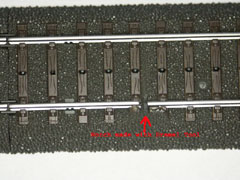
everal pictures of C contact tracks which I made using two different method. The first involves two C track sections while the second, which is more useful, uses only a single C track section.The first set of instructions for making contact tracks from any two C tracks is explained with pictures. You cut a notch with a Dremel Tool disc in the outside rail of two C tracks or the same or different lengths or radii. (A Dremel tool is a rotary device to which you can connect a variety of small tools, i.e., sanding/cutting discs, grinding tools, small drills.) I hot glued the outside rails to be sure that they would not move after making the cut.
On the under side of the two track pieces I found the bridge that connects the outside rails. There is a bridge at each end of the track. Again, using a Dremel Tool disc I cut the four bridges for the outside rails or tracks.
Rather than use a wire with a spade or soldering a wire to a connector, I slipped the bare end of a wire between the "tongue" for the outside rail on the notched side of the track and the plastic part of the connector. I then connected the two tracks with the notches on the same side. The bare wire protruded above the track bed. I then bent the protrudin wire down against the track bed. You can shorten this protruding wire if you wish but I left it long. It is hardly visible. This method saved buying the spades and avoids soldering the rail connectors which could result in melted plastic and mis-aligned tracks.
I have also made contact tracks out of single C tracks, any length and any shape. I hot glue the outer rail, which is very important any lenght of track but especially on short track sections, and then I cut two notches on the same outer rail with a Dremel tool. Then I make a notch on the underside of the track under the same outside rail. I insert the bare end of a wire into this notch. I press the wire into the slot or notch to ensure good contact and then hot glue it. This is actually easier to do then the first method and works just as well. This second method allows greater flexibility on a layout.
You should test the notched sections for isolation and the wires to the S88 for conductivity in either method.