ORIGINAL DIAGRAMS OF MY CURRENT LAYOUT
Click on the back arrow to return to the Main Menu.
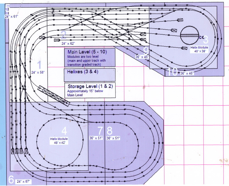
Diagram of the Complete Layout.
T
his is the original diagram for the complete layout. I changed the configuration in several key ways. First, I added a second loop on the upper level. Second, I added a second loop in the city section. Third I completely redesigned the lower level with several loops that allowed me to run two trains on each of the two loops and also allowed for a connection with the main level via a ramp on the right side and a helix on the left. The original configuration called for two helicies but I eliminated the one on the right and moved the one on the left away from the wall toward the front of the layout.
The first picture of each level represents the original design for that level. The second picture shows the actual configuration. The second pictures were taken using the diagrams I created on the Central Station to control each level. The layout mode is a great feature of the Central Station and I use it frequently to run my trains. Setting turnouts and signals takes just a click of the mouse. I have attached a mouse to the Central Station and find it easier to use than the stylus that comes with the CS.
The original diagrams were used to create the bench work and no changes were made to the dimensions that are shown.
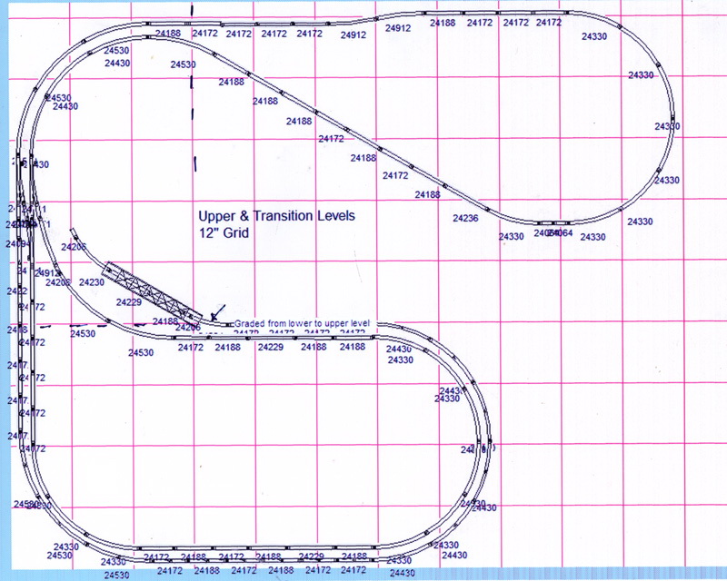
Diagram of the Upper Level of my Current Layout.
This diagram shows the upper-level of my current layout. As stated above, I added a seond loop on the right side which allowed me to run two trains on two different loops. See the pictures from the Central Station layout mode of the actual upper-level configuration Because the loops are so long I actually run two trains on each loop. There is a ramp connecting the upper and main levels. It is represented by a tunnel icon on the left side of the upper level. The numbers represent the decoder switch number for the turnout. Clicking on the turnout or the signal will change it. A solid line represents the open direction for a turnout. Clicking on the arrows in the boxes will bring me to the lower or main levels. The picture at the bottom is a more accurate diagram of the upper level showing the dog bone.
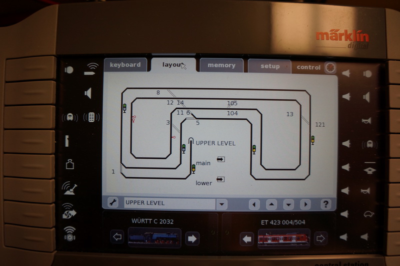
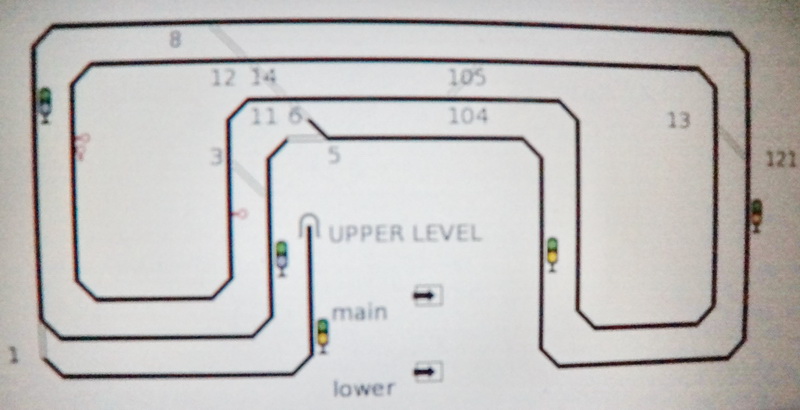
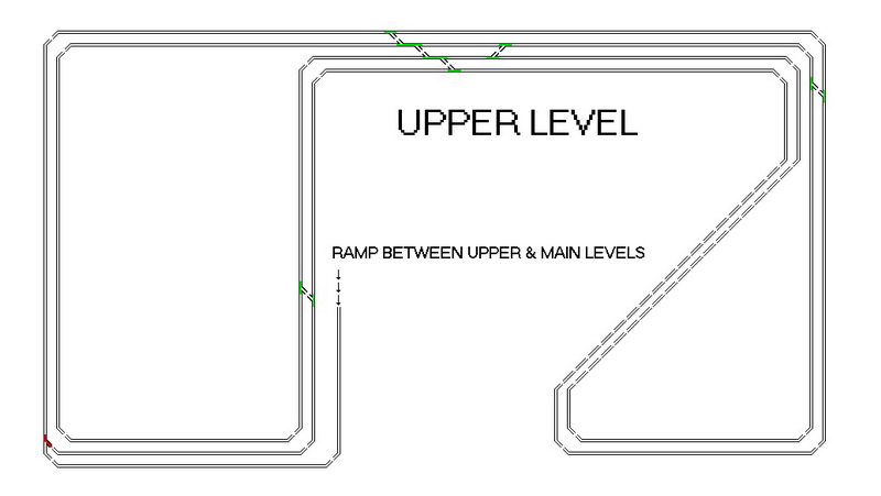
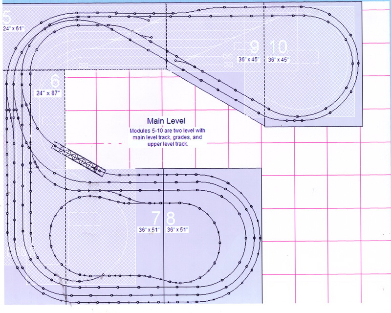
Diagram of the Main Level of My Current Layout.
This diagram shows the Main Level of my current layout. I added a second loop in the City Section and rearranged some of the turnout locations. The diagram does clearly show the cuts for the ramp on the right side and the helix on the left side which was moved to the front of the layout. I also added two sidings that are not shown. Unfortunately, there is only room for one loop so I run two trains on the same single loop on this level. The pictures below are from the layout mode of the Central Station. In the layout mode I can click on a turnout or signal and it throws the turnout or changes the signal. The tunnel icon on the lower left is where a train enters or leaves the main level and travels on the helix either down to the lower level or up to the main level. The lowest left tunnel icon represents the ramp from the upper level to the main level. The tunnel icon on the right is where a train enters or leaves the main level via the long ramp seen in photos. The open position of a turnout is shown as a solid line. Clicking on the arrows in the boxes will bring me to the upper or lower levels. The bottom picture is a more accurate picture of the track configuration.
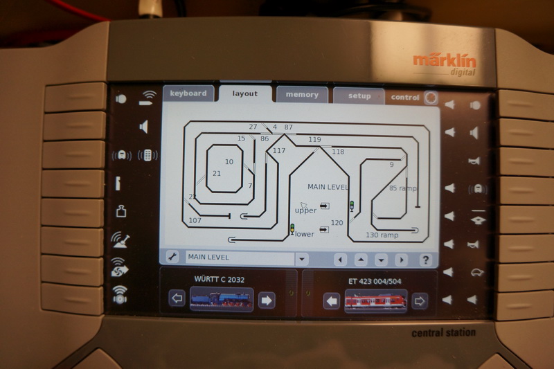
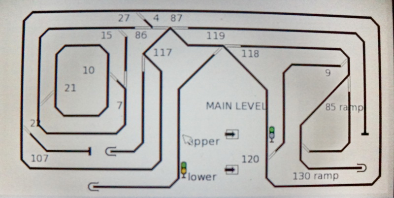
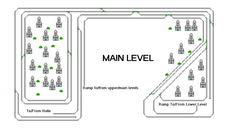
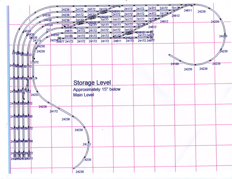
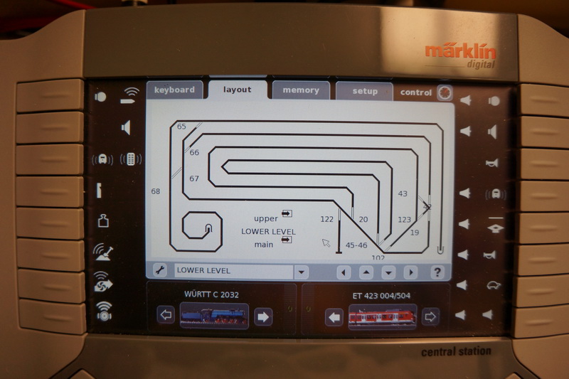
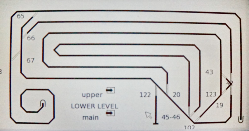
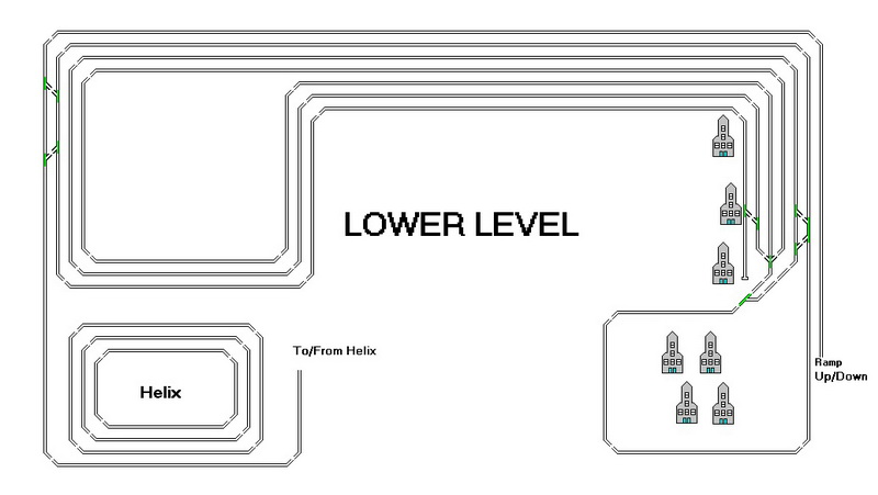
Diagram of the Lower Level of my Current Layout.
This diagram shows the lower-level of my current layout. As stated above, I completely changed the original plan for the lower-level. It was, as the next picture shows, intended only for storage. I configured it so that I could run consists on that level and also have two connections to the main level - one via a long ramp on the right side and the other a helix on the left side. The second picture is the actual configuration. The two pictures below are from the layout section of the Central Station and show the complexity of the lower-level configuration. On the left side the tunnel icon represents the entrance/exit to/from the helix. The tunnel icon on the left represents the beginning or end of the long ramp from the lower-level to the main level. Clicking on the arrows in the boxes will bring me to the upper or main levels. The bottom picture is a more accurate rendering of the lower level configuration.
Click here to return to Home Page.